

Key Takeaways
Good Audi sensor troubleshooting starts with symptoms, scan data, and a careful visual inspection rather than immediately buying a replacement.
- Read stored and pending codes before clearing anything.
- Compare live readings with the engine’s actual behavior.
- Check wiring, grounds, vacuum lines, and battery voltage first.
- Replace a sensor only after confirming its circuit and inputs.
- Complete a drive cycle and recalibration when the system requires it.
Recognizing the signs of a faulty Audi sensor
A sensor fault rarely announces itself in only one way. The vehicle may display a warning, change how the engine runs, or quietly consume more fuel while storing a code. Treat the symptoms as clues that need to be compared with test results, not as proof that one particular sensor has failed.
Warning lights, dashboard messages, and stored faults
A check engine, ABS, airbag, or driver-assistance warning identifies a system that has detected an abnormal condition, but it does not always identify the failed part. A code may describe a circuit, a signal outside its expected range, or a problem that happened only once. Scan for stored, pending, and history faults, and record the exact wording before disconnecting the battery.
A warning that appears after rain, a low-voltage event, or work near a bumper may have a different cause from one that returns immediately after startup. The broader Audi warning light guide is useful background when a dashboard message remains on even though the car still feels normal.
Performance symptoms such as rough idle or sluggish acceleration
Rough idle, hesitation, uneven throttle response, and sluggish acceleration can come from inaccurate airflow, pressure, temperature, or oxygen information. Ignition, fuel, and intake problems can create the same sensations, so replacing a sensor based on drivability alone is risky. Note when the symptom occurs: cold start, warm idle, steady cruising, or hard acceleration.
A sensor that drifts may still send a plausible signal, which is why the vehicle can run acceptably at one speed and poorly at another. Compare the complaint with live data and with physical checks for leaks or loose connections.
Fuel economy, emissions, and starting problems
A faulty temperature or oxygen signal can alter fueling, while an airflow or pressure error can affect load calculations. The result may be reduced fuel economy, an emissions warning, extended cranking, or a start-and-stall condition. Cold and warm behavior are especially helpful: a problem limited to cold starts points the investigation in a different direction from one that appears only after the engine reaches operating temperature.
Do not assume a failed sensor is responsible for every mixture-related fault. Exhaust leaks, intake leaks, weak voltage, and fuel delivery issues can all distort the evidence.
When multiple symptoms point to one underlying issue
Several warnings arriving together often indicate a shared supply, ground, communication, or voltage problem rather than several sensors failing at once. Look for a common connector, harness route, or recent repair. If unrelated modules report faults at the same time, test battery voltage and charging performance before chasing individual components.
The useful question is not simply which warning appeared first. Ask what changed, which faults are current, and whether one physical cause could explain the group.
Identifying which Audi sensor is causing the problem
Audi vehicles use many sensors across engine, braking, chassis, and assistance systems, and the same symptom can cross those boundaries. Model year, engine, transmission, and equipment level affect both the sensor arrangement and the diagnostic procedure. Start by defining the affected system, then narrow the possibilities using codes and measured behavior.
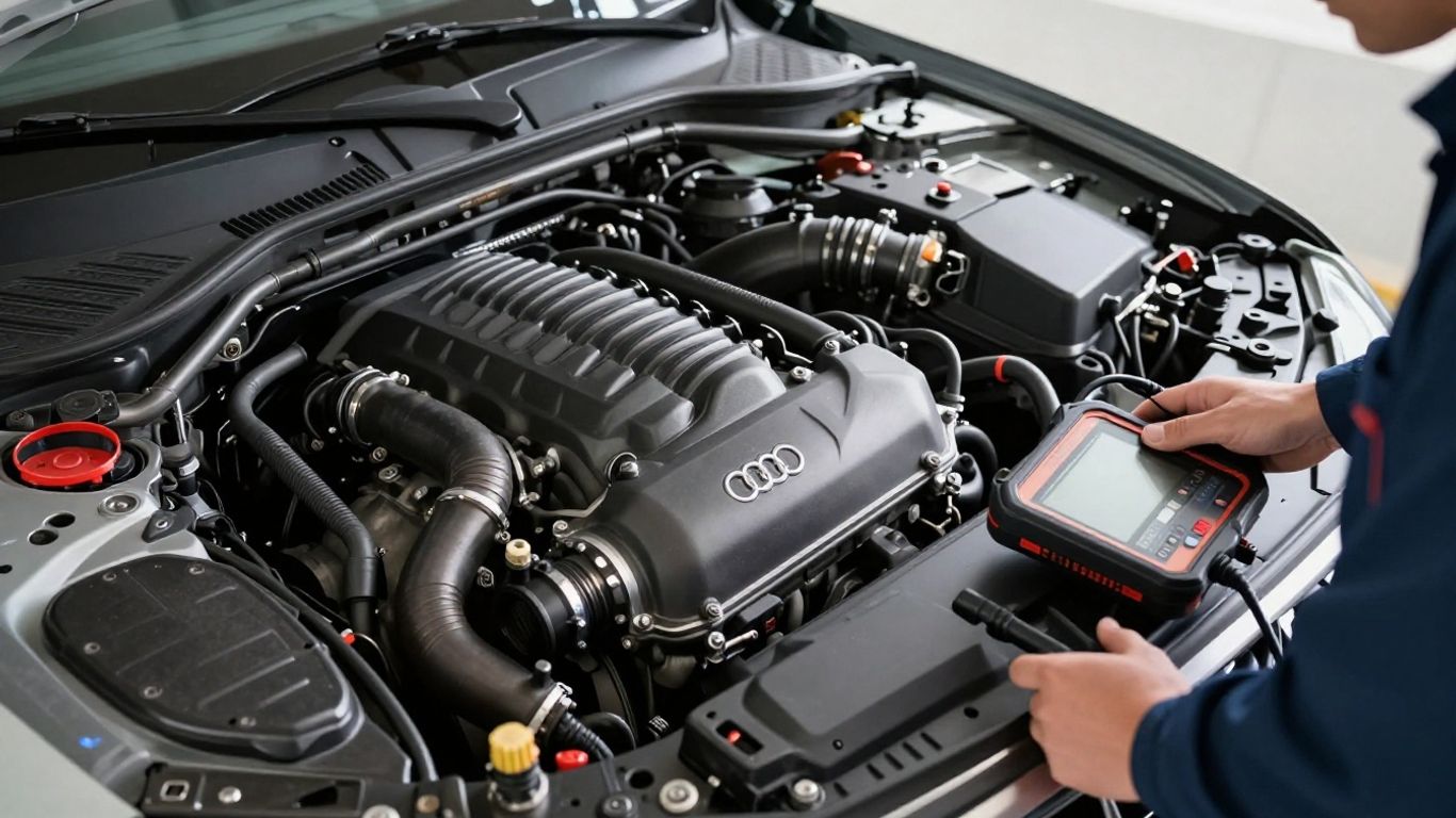
Common sensors linked to check engine faults
Engine-management faults commonly involve airflow, oxygen, manifold pressure, coolant temperature, fuel pressure, crankshaft, and camshaft signals. A code naming a sensor is a starting point, not a verdict; the sensor may be reporting a real engine problem or may be receiving poor power, ground, or reference voltage.
A check engine warning can also come from an ignition or fuel fault that changes the readings of otherwise healthy sensors. Use the scan data to decide whether the signal is implausible, missing, or simply reacting to another fault. The Audi check engine overview provides a useful reminder that a warning can range from a simple sealing issue to a more serious emissions problem.
Distinguishing MAF, oxygen, and MAP sensor symptoms
A MAF problem often appears as hesitation, rough idle, or inconsistent acceleration, but an intake leak can mimic it. Oxygen-sensor concerns are better evaluated through response and fuel-trim behavior once the engine is warm. MAP or boost-related faults should be compared with throttle position, engine load, and requested versus actual pressure.
These sensors do not work in isolation. A useful MAF troubleshooting guide explains why unmetered air can imitate sensor drift and why cleaning may not solve an inaccurate reading. The diagnosis becomes stronger when the symptom, code, and live data all point in the same direction.
Understanding ABS, wheel speed, and steering angle sensor issues
ABS and stability-control warnings may result from a wheel-speed signal that drops out, a damaged tone ring, wiring near the hub, or a steering-angle value that needs calibration. Symptoms can include an ABS lamp, disabled stability functions, or assistance features that switch off. Inspect the wheel area and harness before condemning the sensor.
A steering-angle fault may follow alignment work, battery disconnection, or suspension repairs. Because these systems affect vehicle control, persistent warnings should be addressed before normal driving rather than repeatedly reset.
Using the Audi model year and engine type to narrow the diagnosis
Record the vehicle identification details before ordering a component. Sensor connectors, locations, software behavior, and calibration steps can differ between engines and model years, even when the dashboard symptom sounds identical. Parts catalogs and service information should be checked against the exact vehicle, not only its badge.
This is also where a repair history matters. A recently replaced intake, battery, bumper, wheel bearing, or windshield may explain why a fault began without the sensor itself being defective.
Reading Audi fault codes accurately
A code is a description of detected behavior, not a shopping list. Accurate Audi sensor troubleshooting combines the code with freeze-frame conditions, related faults, wiring checks, and live readings. Save the original scan first, because clearing it removes useful context.
Choosing an OBD-II scanner or Audi-compatible diagnostic tool
A basic OBD-II reader can identify many generic engine codes, while a vehicle-compatible tool may access additional modules and manufacturer-specific information. Choose a tool that can read the system involved, display live data, and save a report. For ABS, steering, parking, or assistance warnings, an engine-only reader may not be enough.
Before scanning, stabilize the vehicle and follow the tool’s connection instructions. A low-cost reader is still useful when its limitations are understood; it should not be treated as proof that no fault exists in modules it cannot access.
Interpreting generic and manufacturer-specific codes
Generic codes provide a common framework, but manufacturer-specific descriptions can add circuit, plausibility, or communication detail. Read the full code, module name, status, and companion faults. A signal code may point toward a sensor, while a reference-voltage code may implicate several components on the same circuit.
Avoid translating one code into a guaranteed replacement. The meaning becomes clearer when you know whether the fault was present continuously, occurred intermittently, or appeared only under a particular load.
Checking freeze-frame data and live sensor readings
Freeze-frame data records conditions such as engine speed, temperature, load, and calculated fuel values when a fault was stored. Recreate those conditions carefully while watching live data, then compare the signal with related inputs. A value that looks normal at idle may become implausible during acceleration.
For a practical scan routine, keep a written record of the original values and the conditions under which the fault returns. That record makes intermittent problems less dependent on memory and helps separate a repeatable failure from a one-time event.
Why clearing a code does not confirm a successful repair
Clearing a code resets the warning state, but it does not repair a circuit or prove that a monitor has completed. Some faults return immediately; others reappear only after a cold start, a specific speed, or a completed emissions test. Clear codes only after recording them, then verify the result through testing and a suitable drive cycle.
If the warning returns, compare the new conditions with the original freeze frame. That comparison often shows whether the repair addressed the cause or merely interrupted the symptom.
Testing Audi sensors before replacing them
Testing should begin with the simplest causes: damaged wiring, poor grounds, disconnected connectors, leaks, and unstable voltage. A sensor can be perfectly healthy while its signal is blocked, shorted, or altered by another mechanical problem. Work methodically and avoid probing sealed connectors in a way that spreads their terminals.
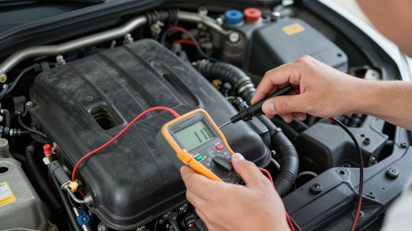
Inspecting wiring, connectors, grounds, and vacuum lines
Look for rubbed insulation, oil or water in connectors, bent terminals, corrosion, and harnesses pulled tight against brackets. Check engine and chassis grounds, then inspect vacuum and intake hoses for splits or loose clamps. A visual inspection is not glamorous, but it can reveal the fault before an expensive component is removed.
Move the harness gently while monitoring the scan signal if the fault is intermittent. Do not tug on wires or force a connector; a damaged terminal can create a second problem during diagnosis.
Comparing live data with normal operating ranges
Use service information for the exact engine and operating condition instead of relying on one universal number. Compare the suspect reading with engine speed, throttle position, temperature, fuel trims, and commanded values. Trends are often more useful than a single snapshot: a signal that responds smoothly may be healthier than one that happens to sit near a typical value.
When possible, capture data during the actual complaint. A normal idle reading cannot rule out a pressure or airflow problem that occurs only under load.
Using a multimeter to check voltage, resistance, and continuity
A multimeter can confirm supply voltage, ground quality, reference voltage, resistance, and continuity, but the correct test depends on the sensor design. Some circuits should be tested powered and under load; others can be damaged by applying voltage. Follow the wiring diagram and specified test values for the vehicle.
Continuity alone is not enough if a wire fails only when warm or flexed. Voltage-drop testing under operating conditions can reveal resistance that a disconnected ohms check misses.
Avoiding false diagnoses caused by air leaks or low battery voltage
Unmetered air can create lean readings and unstable idle, while low system voltage can produce unrelated communication and sensor faults. Check intake plumbing, PCV-related hoses, charging voltage, and battery condition before replacing a component. These checks are especially valuable when several modules report faults at once.
A sensible preliminary sequence keeps the diagnosis grounded:
- Record all codes and freeze-frame data.
- Test battery and charging voltage.
- Inspect intake, vacuum, connectors, and grounds.
- Compare live data during the reported symptom.
This order prevents a misleading code from sending the repair in the wrong direction. It also mirrors the practical value of a good recording session checklist: prepare the information first, then use the working time efficiently.
Troubleshooting common Audi sensor problems
Common faults still require vehicle-specific testing. Cleaning, replacement, and recalibration solve different problems, and none should be assumed from a dashboard message alone. Keep the mechanical condition of the engine and the quality of its electrical supply in view as you work through each pattern.
Diagnosing MAF sensor contamination and airflow readings
A contaminated MAF may produce an implausible airflow signal, hesitation, or rough running, but intake leaks and incorrect installation can look similar. Inspect the air filter housing and ducting, check for unmetered air, and compare airflow behavior with engine load. If cleaning is permitted for that sensor, use the specified method and allow it to dry fully.
A brief improvement after cleaning does not prove the problem is solved. If the reading remains inaccurate or the fault returns, confirm power, ground, signal integrity, and the physical intake path before replacing the unit.
Checking oxygen sensor response and fuel-trim data
Evaluate oxygen-sensor behavior only after the engine is at the appropriate temperature and other faults are considered. Short- and long-term fuel trims can show that the control system is compensating, but they do not identify the cause by themselves. Exhaust leaks ahead of the sensor, fuel pressure problems, and intake leaks can all distort the interpretation.
Look for a consistent relationship between the sensor response and trim changes. A code accompanied by abnormal response is stronger evidence than a code standing alone.
Investigating coolant temperature sensor starting issues
A coolant temperature signal that is implausible when the engine is cold can affect starting enrichment and warm-up behavior. Compare the reported temperature with the ambient temperature before startup, then watch how it changes as the engine warms. A sudden jump, a fixed value, or a value that disagrees with reality deserves further circuit testing.
Check the connector and nearby wiring for contamination or damage. Do not overlook a weak battery, because slow cranking can make a temperature-related starting complaint appear more complicated than it is.
Resolving boost, pressure, and intake sensor faults
Pressure faults should be investigated alongside hoses, clamps, charge-air plumbing, throttle operation, and requested-versus-actual values. A sensor may accurately report a leak rather than cause it. Inspect the entire path and test the circuit before deciding that the sensor is wrong.
Intermittent boost readings also warrant a check for loose connectors and harness movement. Repeatedly clearing the code without checking the mechanical system can make the fault return under the same load.
Addressing pre sense, parking, and driver-assistance sensor warnings
Driver-assistance warnings may follow blocked sensing areas, wiring damage, low voltage, alignment changes, or a calibration requirement. Clean accessible surfaces gently and inspect for recent bumper, windshield, wheel, or suspension work. Do not treat a temporary disappearance of the message as proof that the safety system is fully available.
For general background on a persistent warning, see this pre sense malfunction guide. If the message remains, use the appropriate module scan and have calibration or professional inspection performed when required.
Repairing or replacing a faulty Audi sensor
Once testing confirms the sensor or its circuit, choose the repair that addresses the actual failure. A damaged connector, broken wire, contamination, or failed sensing element each calls for a different response. Keep the original scan and test notes so the result can be checked later.
Deciding between cleaning, repairing, and replacing
Cleaning is appropriate only when the sensor design and manufacturer instructions allow it, and it cannot correct an internal electrical failure. Repair a harness or connector when testing identifies a sound, durable wiring repair as the remedy. Replace the sensor when its signal remains outside specification after power, ground, mechanical inputs, and wiring have been confirmed.
The goal is confirmed root-cause work, not simply a vanished warning. If a replacement seems to fix several unrelated faults at once, rescan the vehicle and verify each affected system.
Selecting an OEM or aftermarket replacement
Match the replacement by vehicle identification details, engine, connector, calibration needs, and documented specification. Quality and compatibility matter more than the lowest initial price. A part that fits physically but sends a different signal or lacks the required calibration can create another round of diagnosis.
Use a reputable source and retain the packaging and part information. That makes it easier to check the component if the fault returns or the scan reveals a mismatch.
Following installation and calibration requirements
Follow the service procedure for orientation, torque, sealing, connector engagement, and software or basic-setting steps. Wheel-speed, steering-angle, camera, radar, and some engine-management components may require adaptations or calibration after installation or related repairs. A scan tool should be used only as directed for those procedures.
If calibration requires special equipment or a level surface, do not improvise. The vehicle may drive normally while the assistance system remains unavailable or inaccurate.
Preventing damage from incorrect handling or installation
Protect sensing elements from impact, solvents not approved for the part, static discharge, and excessive force. Never pull a sensor by its wires, leave a connector partially latched, or install a seal that is twisted or missing. Route replacement wiring away from heat, moving parts, and sharp edges.
After installation, inspect the work before starting the vehicle. A careful final check can prevent a new fault caused by a pinched harness or an intake connection left loose.
Verifying the repair and preventing repeat sensor faults
A repair is complete only when the original symptom is gone, the relevant data is plausible, and the system passes its checks. Verification may take a short inspection or a longer drive cycle depending on the fault. Keep the process deliberate rather than relying on the dashboard alone.
Clearing codes and completing an appropriate drive cycle
Record the final pre-repair scan, then clear codes with the correct tool and follow a drive cycle that includes the conditions needed by the affected monitor. A vehicle may need cold operation, steady cruising, deceleration, or repeated starts before a monitor runs. Stop if a warning flashes, the engine runs dangerously, or braking and assistance functions are compromised.
A code that stays away for a few minutes is not the same as a completed verification. Check readiness and rescan after the relevant conditions have been met.
Confirming normal readings after the repair
Compare post-repair live data with the original capture and with the normal range for the exact vehicle. Confirm that the reading responds to changes in load, temperature, speed, or throttle as expected. Also verify that fuel trims, misfire counters, pressure values, or wheel-speed signals no longer show the original pattern.
A road test should reproduce the complaint when safe to do so. If the symptom remains but the code changes, treat that as new evidence rather than assuming the first diagnosis was correct.
Calibrating sensors that require basic settings or adaptations
Some sensors need a basic setting, relearn, or calibration after replacement, alignment, battery work, or a change to surrounding hardware. The procedure depends on the module and vehicle configuration. Confirm that the operation completed successfully, then scan again for calibration and plausibility faults.
A failed calibration can point to incorrect installation, unsuitable conditions, or a remaining mechanical or wiring problem. It should be investigated, not hidden by repeated resets.
Keeping connectors, intake systems, and battery voltage in good condition
Preventive care is mostly simple: keep connectors dry and secure, repair intake leaks promptly, maintain the air-filter housing, and monitor battery and charging condition. Avoid pressure-washing sensitive areas and inspect harnesses after work near the engine, wheels, bumper, or windshield. Regular service reduces the chance that a small mechanical issue will be mistaken for an electronic failure.
For broader maintenance context, even unrelated home-care guides such as Attic Fanatics, Cedar Park roof checks, omega-3 storage advice, and bridal makeup preparation illustrate the same practical principle: preparation and condition checks prevent avoidable repeat problems.
Conclusion
Audi sensor troubleshooting is most reliable when symptoms, fault codes, physical inspection, and live data agree. Test the circuit and the surrounding mechanical system before replacing a part, then complete the required drive cycle or calibration and confirm that the original behavior has disappeared.
Frequently Asked Questions
Can I drive with an Audi sensor warning?
It depends on the warning. A persistent engine light may allow careful travel to a repair location, while flashing engine, ABS, braking, steering, or driver-assistance warnings may require stopping and professional assessment.
Does a fault code identify the failed sensor?
Not always. A code can describe a circuit, implausible signal, wiring issue, or condition caused by another component, so testing is needed before replacement.
Can cleaning fix a dirty airflow sensor?
Sometimes, if contamination is the confirmed cause and the sensor is safe to clean. Cleaning will not repair internal electrical failure or an intake leak.
Why did the warning return after clearing it?
The underlying condition may still be present, or the system may have needed specific driving conditions before detecting it again. Recheck the code and compare its new freeze-frame data.
How can I find an intermittent sensor fault?
Save scan data, inspect connectors and harness movement, monitor live readings during the complaint, and test voltage and grounds under operating conditions.
Do replacement sensors need calibration?
Some do, particularly sensors connected with steering, braking, camera, radar, or driver-assistance functions. Follow the service procedure for the exact vehicle and module.
When should a professional diagnose the vehicle?
Seek professional help when warnings involve braking or safety systems, the fault returns after testing, calibration is required, or the available scan tool cannot access the affected module.